Aerospace NU

Project Redshift is AeroNU‘s central rocketry project. The group is entirely student-run, and is working towards competing in DPF, an intercollegiate rocketry competition.
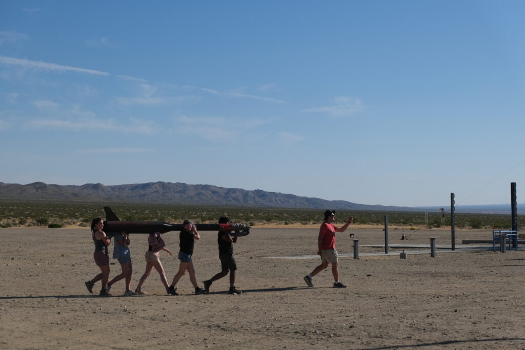
Carrying a rocket across the FAR launch site on a sweltering Mojave afternoon

I joined Redshift in the spring of my first year, under the internal mechanics subgroup. I met many talented and kind engineers, and learned a tremendous amount about rocketry. With this group I built an airspeed sensor, and conducted parachute experiments.

I then moved to the propulsion subgroup, who was working on a bi-propellant liquid-fueled rocket engine. I became enthralled with the complexity of this process, involving advanced fluid simulations and combustion calculations.

The liquid propulsion group has made remarkable progress considering it’s only ~4 years old. Our first project made for flight is a regeneratively cooled kerosene-LOX engine (commonly called the regen engine), and uses a pintle injector machined from aluminum in house.
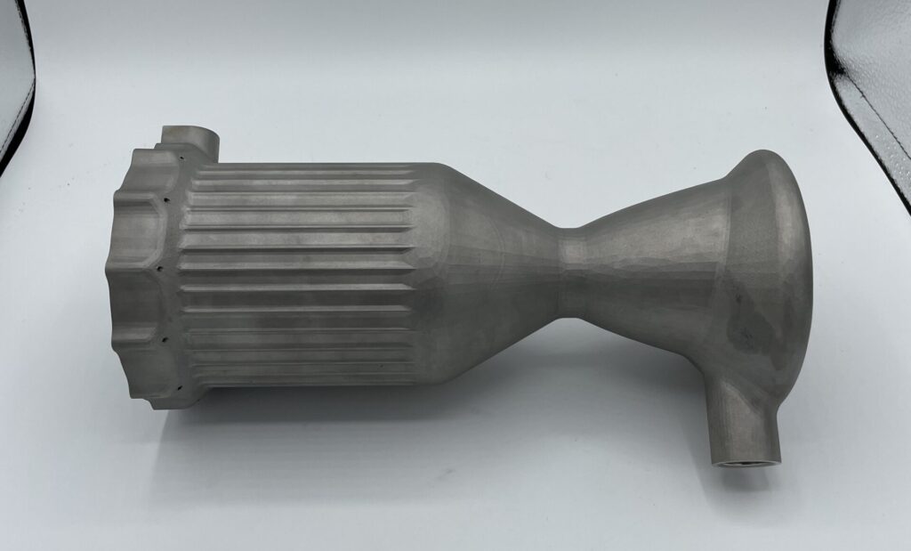
Regen engine

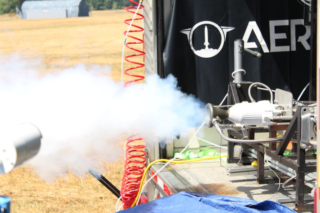
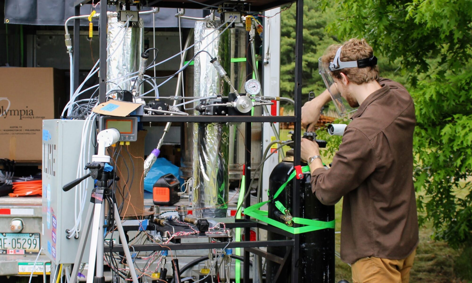
Over my time in propulsion, we’ve been in the testing and validation phase of the regen engine. This includes countless waterflows, cold flows, and 2x static fires to date. These are all performed on our horizontal test stand, a pressure-fed feed system meant for maximum data acquisition. Setup procedures are often at least partly manual, but pressurization and flow is controlled entirely remotely through a pop-up ground-station.
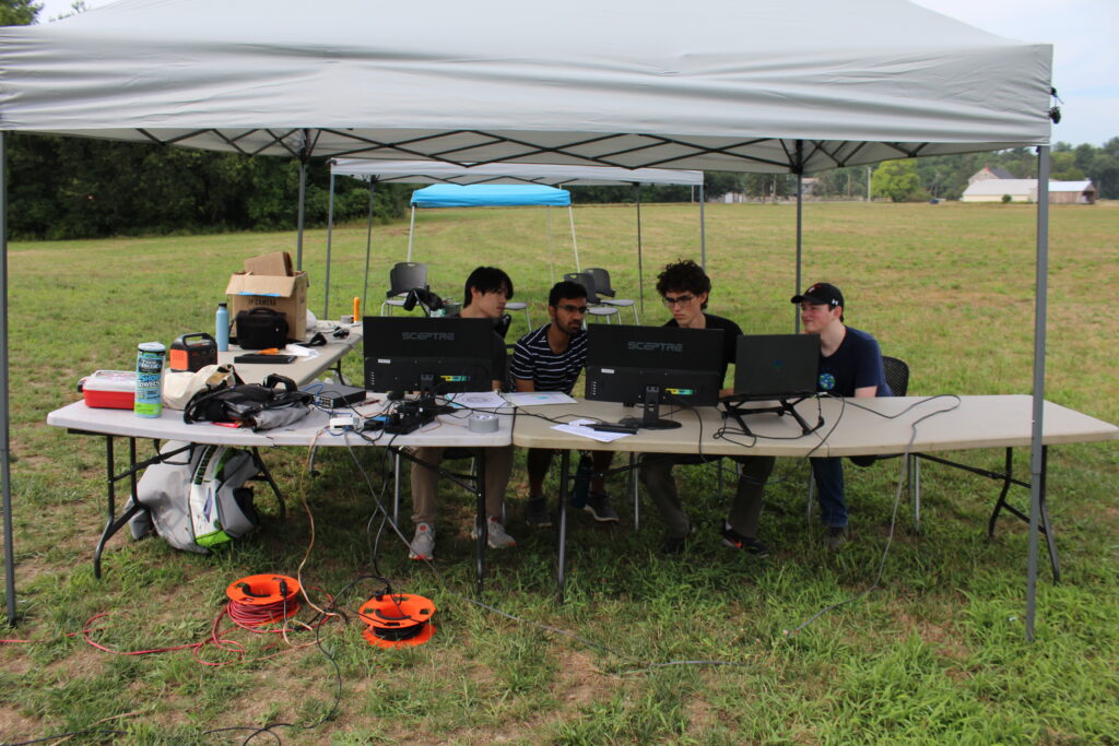
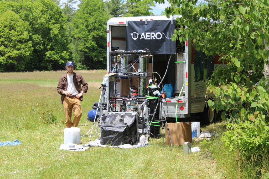
Cold flow

The goals of these tests is often to characterize flow through different parts of the test stand and different conditions. This if often seen through variables such as pressure drop, Cv, mass flow rates, atomization, etc. These are determined experimentally, and help us to perform operations successfully.

To date we have run two static fire tests, neither of which were successful, likely due to hard starts. See the explosive videos below.

Explosive test-fires

Even though not nominally successful, the amount we learn from these is substantial. From these, clear paths forward emerge and we gain intangible insight on how to improve. It’s always inspiring to see the mountain of collaboration and effort that goes into each test, regardless of the degree of success.

Since December 2022 I’ve been leading the project, overseeing key decisions in the development timeline as well as delegating numerous sub-systems including: a swirl injector, automated spark igniter, CO2 fire suppression, and a motor-controlled proportioning valve.

A key part of keeping the project running is education. Many of the systems we work on require in-depth knowledge of fluids, thermodynamics, etc. Unfortunately, most students aren’t exposed to these concepts academically until late in their education. As a result, we make an effort to continually support and teach our newer members so that they can contribute.
Machining: lap joints

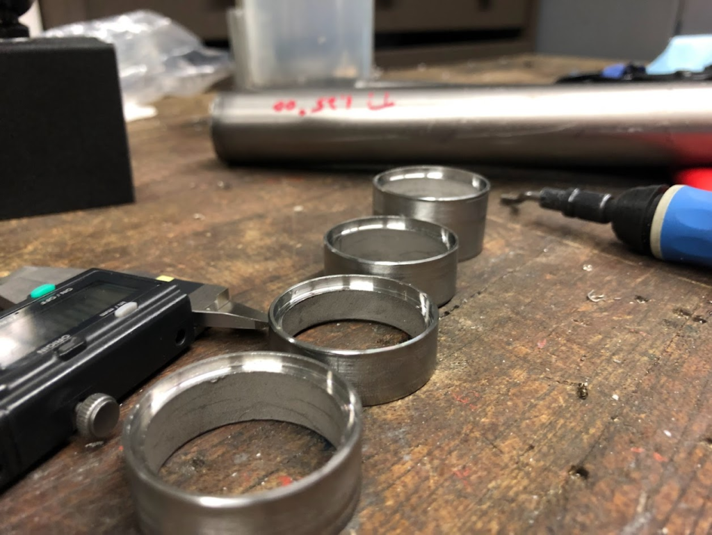
This project for Mesodyne was my introduction to machining. All of these parts were done on a manual lathe, part of materials science bonding experiments I was conducting. Samples had to be identical and numerous for consistent results. The operation consisted of a simple .060″ lap joint put into SS 304 and titanium tube stubs. The scale of this project included dozens of samples, with minimal variability.

Consistent lap joints

Machining: flanges

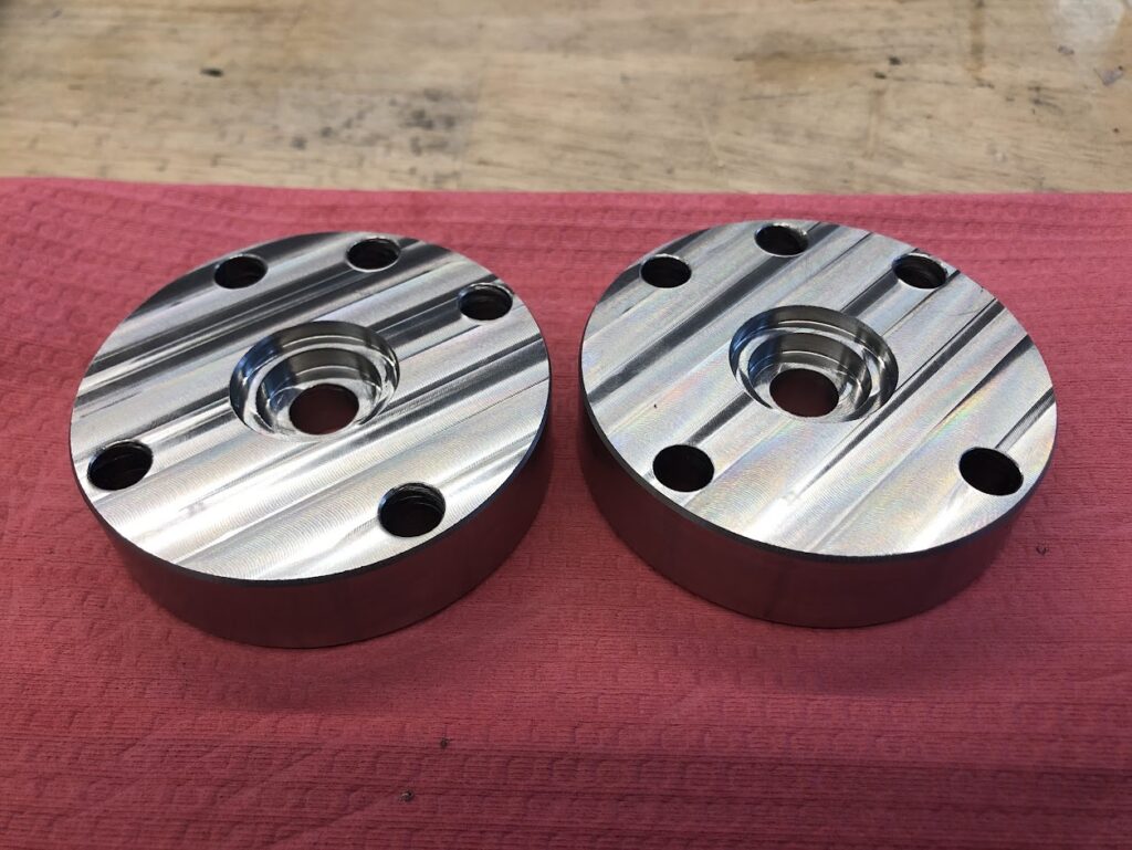
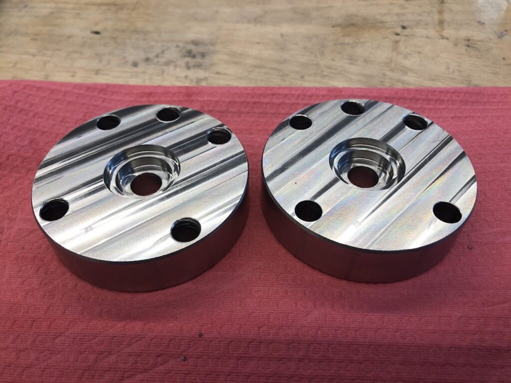
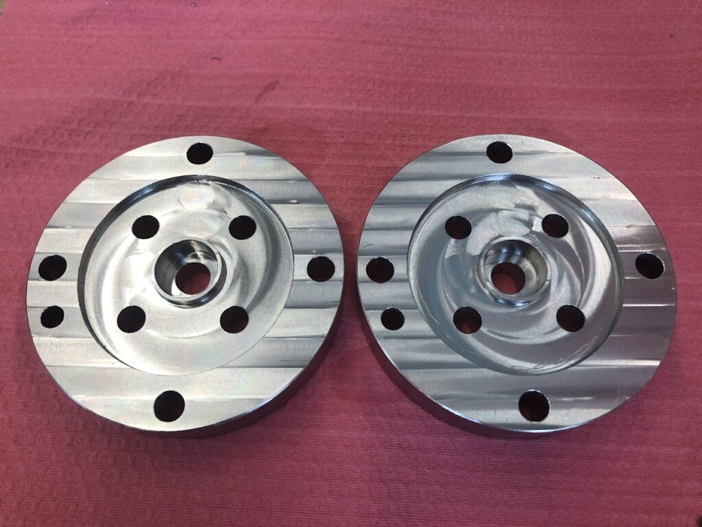
These custom flanges were made for an iteration of Lydian’s catalytic reactor design. They include specific countersinks to maintain alignment and even compression onto the substrate. 1/4″ BSPP tapped holes are implemented to facilitate gas flow through the reactor.

Flange iteration
Larger flange iteration

They were machined from SS 316 on a Haas CNC Mini mill. Several iterations were made in house for rapid testing, and eventually sent out for production-scale.

Machining: electrodes

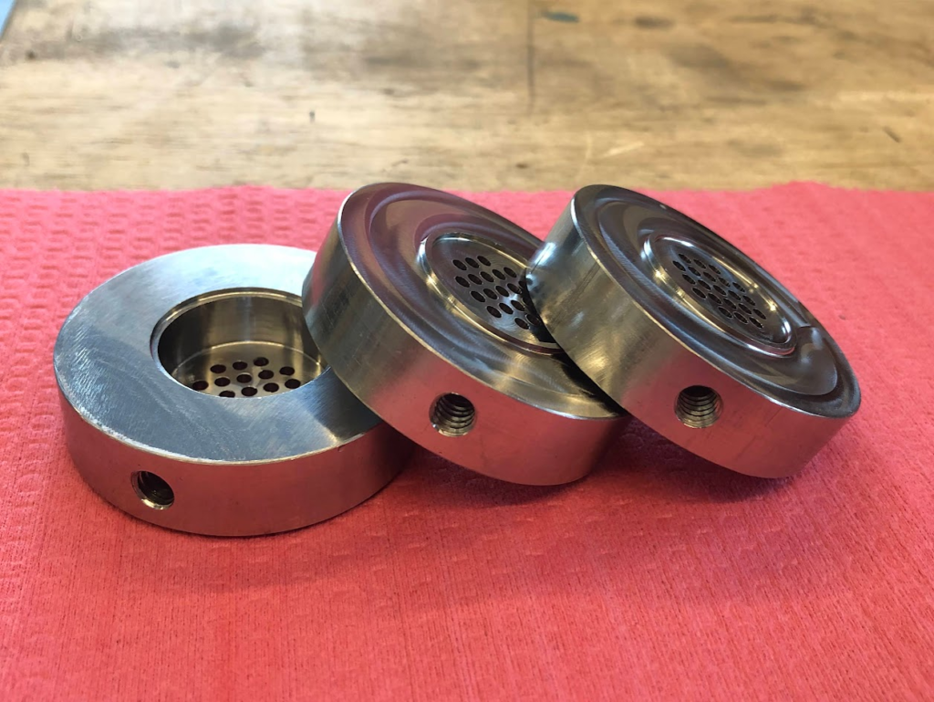
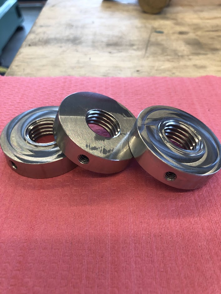
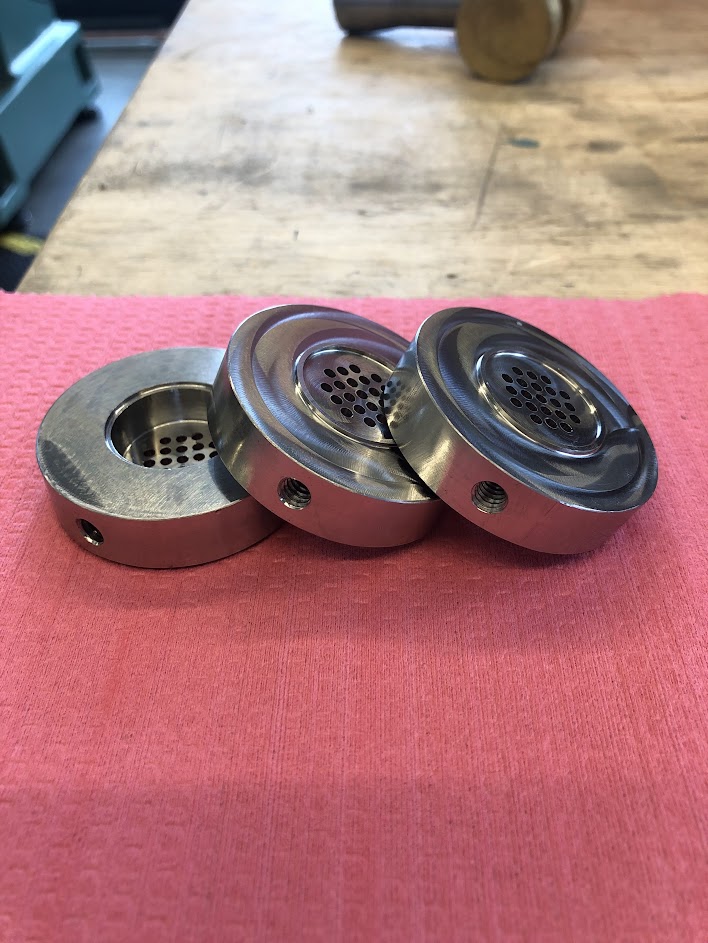
These parts were used as electrical contacts to power Lydian’s resistively heated catalytic reactor. They were made from SS 316 with a Haas CNC Mini-mill. A perpendicular threaded hole was used to interface with electrical feedthroughs. Perforations were used in the bottom set to apply even pressure on the substrate and allow reaction gas to flow through.

The top set includes a set screw implement to apply pressure.

Manifold

For this project, I designed and implemented a manifold to distribute fuel and air into a combustion setup at Mesodyne. This experience involved more complex design elements including balancing lead time and longevity, manufacturability, and fluid flow dynamics.

It was necessary for this part to be created as quickly as possible. As a result, I decided to print it in-house from PLA. This obviously directed the design towards being printable, as well as being “just good enough”. The shift away from perfectionism is an important idea, and something I hadn’t done previously.

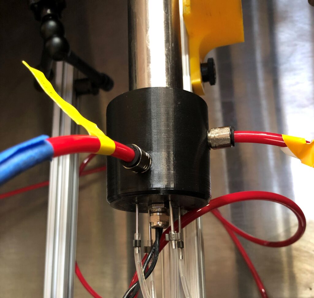
The goals of the part are to uniformly distribute air and fuel into concentric tubes, and allow room for additional DAQ electronics. This was done by using internal tori to redirect fluid flow.

Cross-sectional view: showing upper and lower tori, fuel syringe holes, as well as o-ring grooves for tight seals.

This device worked well to uniformly distribute airflow in two separate tubes for combustion, while fuel was injected through needles moving vertically through the base. An additional piece was used to attach to an 8020 aluminum bar. The DAQ electronics including thermocouples and glow plugs are inserted through the bottom.

The tori included tapped openings to insert NPT fittings, shown below.

Manifold in situ. Red tubing is for air, clear tubing is for fuel, black wire is for electronics.

The manifold worked well for its purpose. The accelerated timeline for a part like this meant perfection would take too long, and thus is unnecessary. This concept is critical to effective and realistic engineering.

Calorimeter

In this project I engineered and operated a calorimeter system to measure heat transfer across thermophotovoltaic generators for Mesodyne. I independently wrote and edited Python and Arduino scripts to collect and organize data for real-time adjustment and long term recording.

The principle behind any calorimeter is to determine the heat produced from a process via an external fluid. In this case, I flowed water past a combustion and measured its temperature at the inlet and outlet; extrapolating rate of energy transfer for the reaction (dQ/dt) through a simple formula:

dQ/dt = (dm/dt)cΔT

Where (dm/dt) is the mass flow rate, c is the specific heat, and ΔT is the change in temperature.

I had inherited a narrowly functional system plagued with issues including flow problems, inaccuracies, and unreliable hardware.

Hardware

A large part of this project was finding solutions through iteration. For example: an integral component of this calorimeter is determining accurate waterflow through a flow meter. A tight specific range is desired to produce the highest accuracy for a given uncertainty, thus I sought to pump water as slow as possible. Finding a flow meter to detect very slow circulation, stay within our necessary uncertainty, and communicate data to my setup was nearly impossible. Instead, compromises had to be identified through several iterations of sensors and configurations. This process was true of each component including pumps, reservoirs, thermistors, tubing, and fittings.

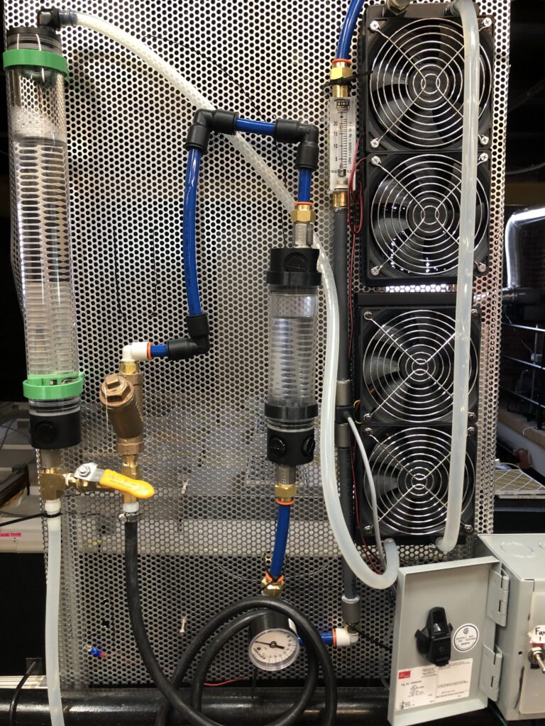
Component diagram: R = reservoir, BC = bubble catcher, P = pressure gage, DF = digital flow meter, AF = analog flow meter, C = calorimeter

A major issue causing inaccuracy for the inherited version was air being trapped in the flow path. This skews results for obvious reasons, and is difficult to avoid with a traditional setup. I implemented a specific configuration using the behavior of air bubbles to rise in water, which included a filter and an additional reservoir to catch bubbles. This worked very well to eliminate air from the water lines.

Countless small solutions were implemented to improve the system including: using flexible tubing to dampen pump vibrations, inserting a bypass to better control flow rate, adding sealant to ensure leaks from delicate fittings, etc.

Software

To reliably communicate live data, an inherited custom PCB was used along with a basic Python script, which was heavily modified. I opted to use a USB serial connection due to its reliability and simplicity, which allowed an Arduino mini to communicate raw data. This is taken by the Python script and transformed into graphs that update in real time then record to a spreadsheet. Additionally, up to 6 thermocouples were used concurrently to monitor specific temperature points on the combustion setup through a separate interface.

To communicate findings to the company, I organized results onto a timeseries to convey critical moments and values from multiple perspectives.

Summary

Final system

Overall, the system worked to a much higher degree of accuracy than inherited. There are nuances in operation that include optimizing flow rate with burn temperature, and defining specific software configurations. The project took longer than I had hoped, mostly due to long lead times on components. During my time at Mesodyne, the calorimeter data was well received and used frequently without issue.

(due to the proprietary nature of this project, select images and information have been omitted which may lead to a less clear understanding of the system.)

Orifice Plate

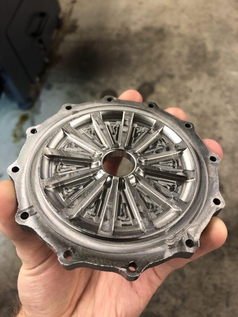
In this project, I modified and machined the orifice plate to Aerospace NU’s rocket engine. The original design used two plates sealed with a graphite gasket, which offered excess complexity and additional failure modes. By merging the two parts, this creates a perfect seal.

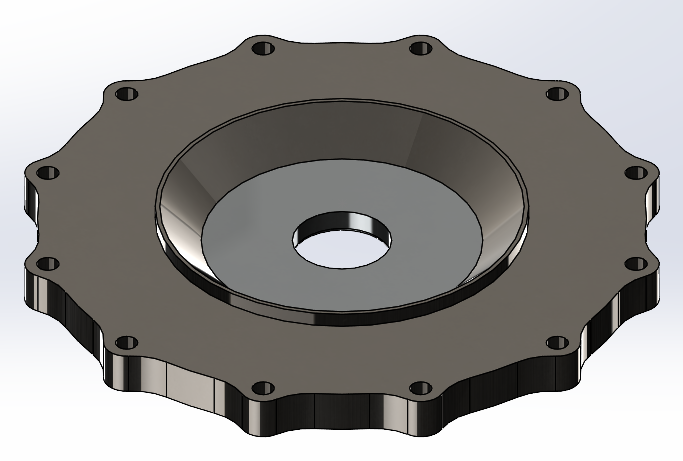
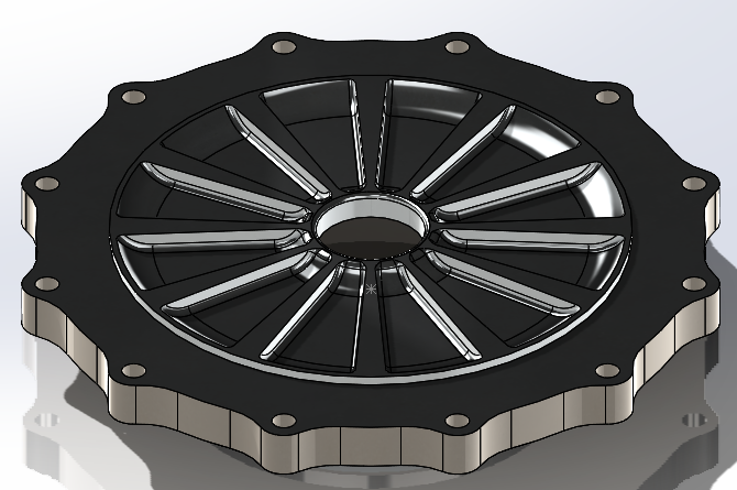
The orifice plate is used to distribute then atomize the oxidizer uniformly in the engine chamber. This is then mixed with the fuel to create even combustion. The design consists of 12 channels converging on a central orifice, then passing through an expanding conical section to the chamber.

For such a precise part, CNC machining is necessary. I used HSMworks to program the operations necessary. The original stock had the perimeter waterjet, and the central hole was drilled out.

Top side operations
Bottom side operations

This was my introduction to CNC machining, and many of the nuances found in automated machining were made clear to me during the process; including 3D machining for smooth inclines and surface finish techniques.

The plate was then ready to use in our engine for static fire testing.

Finished product

Problem Statement

As the global population grows and the climate warms, the agricultural world faces a grim future. The use of select genetically modified (GM) crops should be welcomed as a measure against land-use change (deforestation), agricultural emissions, and global food insecurity. The movement against GM crops is largely founded in the ideas of uncertainty for long-term safety, and the conducive use of harmful pesticides and herbicides. This opinion tends to be rooted in oversimplification and disinformation, grouping all GM crops into one category. Additionally, economic incentives are difficult to produce for the development of such crops; lack of intellectual property security and limited markets from regulations are leading factors hindering the expansion of GM crops. As an example, the European Union has not yet widely adopted GM crops, and thus has to import much of its food supply. 30 million tons of soybeans are imported each year; the majority of which coming from Brazil, in which forests are being destroyed to create more farmland.

Unlike herbicide and pesticide-tolerant crops, GM crops designed to resist abiotic (environmental) factors such as moisture content and temperature variability have very few downsides. The widespread political adoption would increase the economic potential and thus increase their use. This would stimulate all economic levels as farmers find higher yields, and areas such as Europe begin importing less, and exporting more. This, in turn, would also significantly reduce the amount of land-use change, in addition to providing difficult-to-grow climates with more agricultural independence.

Global food insecurity is accelerating due to climate change. The full integration of GM crops (specialized to resist abiotic stress) will reduce emissions by slowing land-use change, provide more food to the world population, and grow the economies of fertile lands. This can be achieved socially by more clearly defining the risks and rewards of GM crops to the public, which in turn will influence the political realm.